UNOBAT 50 BATTEN SPORTS FLOOR
SPECIFIER'S AND INSTALLATION INSTRUCTIONS
D 14.1
D 14.1
1. SPECIFIER'S INSTRUCTIONS
INFORMATION
UNOBAT 50 BATTEN SYSTEM
|
D 1.0 |
General information |
|
D 14.1 |
Specifier's - and |
Table 1
1.1 SYSTEM SPECIFICATION
Junckers Unobat 50 sports floor is based on 22 mm solid hardwood floorboards fastened to a subfloor system consisting of single layer engineered battens with pre-attached special designed shock absorbing foam strips.
The shock absorbing foam strips are inset into a “U” shaped channel on the underside of the batten. This design creates a built-in stop block, ensuring the long-term resilience of the system.
The Unobat 50 system can be installed on a dry, load-bearing floor of concrete, lightweight concrete, wooden materials or on an existing synthetic or wooden sports floor.
Batten distance: c/c 336.
Construction height: 50 mm.
Performance:
The floor system is an area elastic sports floor with a high level of shock absorption and resilience. Very suitable for multifunctional sports halls, arenas and squash.
Junckers Unobat 50 is tested and approved according to:
- The European Sports Norm EN 14904:A4
- FIBA Level 1.
Step sound reduction by installation on heavy constructed horizontal divisions:
22 mm floorboards on UnoBat 50 battens: 19 dB.
For general information about sound and practical guidelines on acoustics in floor constructions, see data sheet E 5.0.
Read all information:
Please note that full documentation of this floor system comprises General information, Specifier's and Installation instructions,
see table 1. By questions, please contact Junckers Technical Service.
1.2 FLOOR COMPONENTS - UNOBAT 50 BATTEN SYSTEM
-
Junckers 2-strip solid hardwood floorboards for sport
Thickness x width x length
22 x 129 x 3700 mm
Wood Species, grade and surface:
See data sheet B 2.0 -
Junckers J-Nails (Machine nail)
2.2 x 45 mm special developed J-nails with a high shearing- and pull out strength. -
Laminated battens
21 x 45 x 3600 mm with 9 x 9 mm pre-attached shock absorbing strips.
Total batten height: 28 mm
Batten distance: c/c 336.4 mm (336)
Unobat 50 battens are made of spruce with a moisture content of 8-10 %. -
SylvaThene moisture barrier:
0,20 mm PE-foil. -
Expansion gap at the wall
1.5 mm per metre width on each side and 1 mm per metre length at each end, but both min. 30 mm. Is also required at fixed points, e.g. column.
Fig. 1

1.3 LOAD BEARING STRENGTH
The Unobat 50 Sports Floor System is designed to ensure good technical properties in relation to the expected loads in connection with sports activities.
Bearing capacity at point loads
The Unobat 50 batten system is tested and approved for below mentioned maximum point loads, in relation to load area and batten centres c/c 336 mm.
For heavily loaded areas such as scenes or stands, it may be necessary to install extra battens. These are UnoBat 50 battens, turned upside down and installed between the original battens.
Table 2 shows the maximum load-bearing capacity from point loads at the batten system's recommended batten distance.
|
Table 2 |
|
Batten distance c/c 336 mm: |
|
ø 25 mm: 5.0 kN (approx. 500 kg) |
|
100x100 mm: 6.0 kN (approx. 600 kg) |
Table 3 shows use of the floor system in relation to the load classes in EN 1991-1-1, corresponding to load bearing requierements and the floor having acceptable stiffness. Furthermore the applicability of the floor system in relation to wheel load is noted.
For further definition of load classes and types, see General Information Junckers sports floors D 1.0 - Stiffness and loadbearing strength.
|
Table 3 |
Loading types |
|
|
Loading category |
Area- and Point load |
Wheel load |
|
C4: Assembly halls for physical activity, e.g. gyms/theatres |
Approved* |
Approved** |
|
C5: Assembly halls which can be crowded, e.g. sports halls incl. stands |
Approved* |
Approved** |
* Point load area min. 200 x 200 mm / ** Wheel loads, see D 1.0 - Table 2
Fig. 2
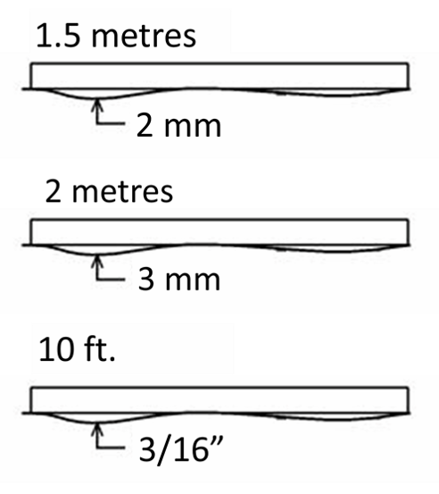
1.4 FLATNESS OF THE SUBFLOOR
Battens must be straight with no distortion and the subfloor must be levelled so that any deviations in the flatness do not conflict with the requirements of the method stated below.
Straight edge:
The subfloor must be flat with a maximum deviation of 2 mm under a 1.5 m straight edge.
(UK: 3 mm under a 2 m straight edge acc. BS 8201).
(US: 3/16” under a 10 ft. straight edge).
Deviations are measured as gaps under the straight edge. The surface must be smooth. Any irregularities must be corrected by grinding or by using a self levelling compound.
Fig. 3
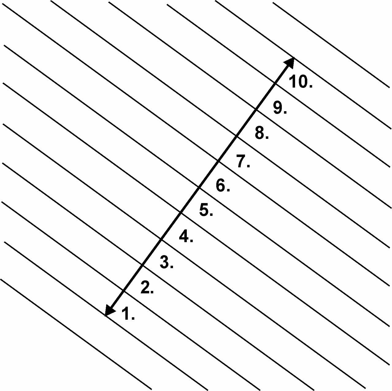
1.5 THE 10-BOARD RULE - AVOID STRESS AND GAPS
In order to minimize stress or gaps in the floor due to fluctuations in the climatic conditions within the building, floorboards must be laid according to a 10‑board rule.
This indicates the measurement across 10 floorboards when laid and should be checked continuously during the installation and afterwards, see Fig. 3.
To keep the 10-board measurement (10 BM), it is recommended to use Junckers temporary spacers during installation of the floor. Spacers are delivered in a range of sizes to suit the expected relative humidity of the room.
Fig. 4
The 10-board measurement is chosen on the basis of the expected maximum relative humidity in the building when in use throughout the year, see fig. 4
The graph in figure 4 illustrates the 10-board rule in relation to the relative air humidity for 129 mm wide floorboards. E.g. an expected relative humidity of max. 65 % RH will normally require a 10-board measurement of approx. 1294 mm.
The outer limits of the 10-board measurement, which also depend on the floor size, are marked with dotted lines.
The size of the floor area, as well as it’s location, i.e. ground floor or floor horizontal division, may also have influence on the choice of the 10-board measurement.
For further information please contact Junckers technical service department.
1.6 MOISTURE PROTECTION
Concrete subfloors
When checked by measurement the residual moisture contained in the concrete or screed must not exceed 90 % RH.
(In UK: Concrete moisture max. 75 % RH acc. to BS 8201)
At ground level and other upper levels, protection against moisture both from within the building and from the ground is required.
A moisture barrier is established by laying a damp-proof membrane, 0.20 mm PE membrane or 1000 g polythene, e.g. Junckers SylvaThene moisture barrier, directly on the concrete before laying out the battens.
Wooden subfloors
For renovation projects where new floor systems are laid on existing wooden subfloors, it must be ensured that the entire structure has been designed to the correct specifications regarding moisture.
Usually, no additional moisture protection must be applied on top of the existing sports floor, as this may course the risk of fungal attacks in the subconstruction.
1.7 VENTILATION OF THE SUBFLOOR
In general, batten sports floor systems should be installed using skirtings with ventilation slots, to ensure adequate ventilation of the substructure. Moreover, to minimize the consequences of environmental fluctuations in the building as much as possible, the same climate should be maintained both above and below the floor surface.
The expected relative humidity range will usually be complied with through natural ventilation via the aforementioned ventilation slots. By natural ventilation we mean the air flow will be as a consequence of movement of the floor surface during normal sports activities.
In all circumstances it is important that the ventilation slots at the walls be retained and that the moisture-protection instructions are observed, see Moisture protection.
1.8 NET CONSUMPTION OF MATERIALS
Net consumption for Unobat 50 sports floor system:
- Floorboards: Area + approx. 2 % wastage
- Unobat 50 battens c/c 336: 3.0 rnm per m²
- J-Nails c/c 336: 25 pcs. per m²
- Loose tounges of 600 mm: 1 x the length of the sports hall
- SylvaFix header joint adhesive: 1 bottle per 300 m²
- SylvaThene moisture barrier: Area + approx. 10 % wastage
2. INSTALLATION INSTRUCTIONS
WHEN TO START INSTALLATION
The building must be weather tight. The heating system must be installed and tested, and during the heating season there should be a constant heat supply.
Cast concrete elements, including casting of sockets for fixtures and fittings, screeding and other wet trades which can contribute moisture to the building, e.g. priming of paintwork, must also be completed.
The relative humidity in the building must be between 35-65 % RH (UK) and the temperature approx. 16-20 °C.
The residual moisture contained in the concrete or screed must not exceed 90 % RH. (In UK: 75 % acc. to BS 8201). In wooden based sub floors the moisture content should not exceed 12 %.
Solid floorboards should always be laid immediately after arrival at the building. The wrapping of the floorboards must not be removed until just prior to laying the floor, i.e. no acclimatising of the floorboards on site must take place.

2.1 MOISTURE BARRIER
On concrete sub floors a moisture barrier of min. 0.20 mm PE membrane is laid, e.g. Junckers SylvaThene moisture barrier.
The moisture barrier is laid with an overlap of 200 mm at all joints, continuing up walls, etc.
The polythene has to be taped at all lap joints.
2.2 EXPANSION GAPS AT WALLS AND FIXED OBJECTS
The minimum expansion gap at walls and fixed objects must be 30 mm in order to allow for movement of the floor, but also to provide for ventilation of the substructure. In the case of especially wide spans it may be necessary for a gap of more than 30 mm to be formed.
This is calculated at 1.5 mm per m width at each side and 1mm per m length at each end of the floor.
For floors less than 10 m wide the minimum expansion gap size can be reduced to 15 mm.
The gap between wall and floor is covered with Junckers combi sports skirting.

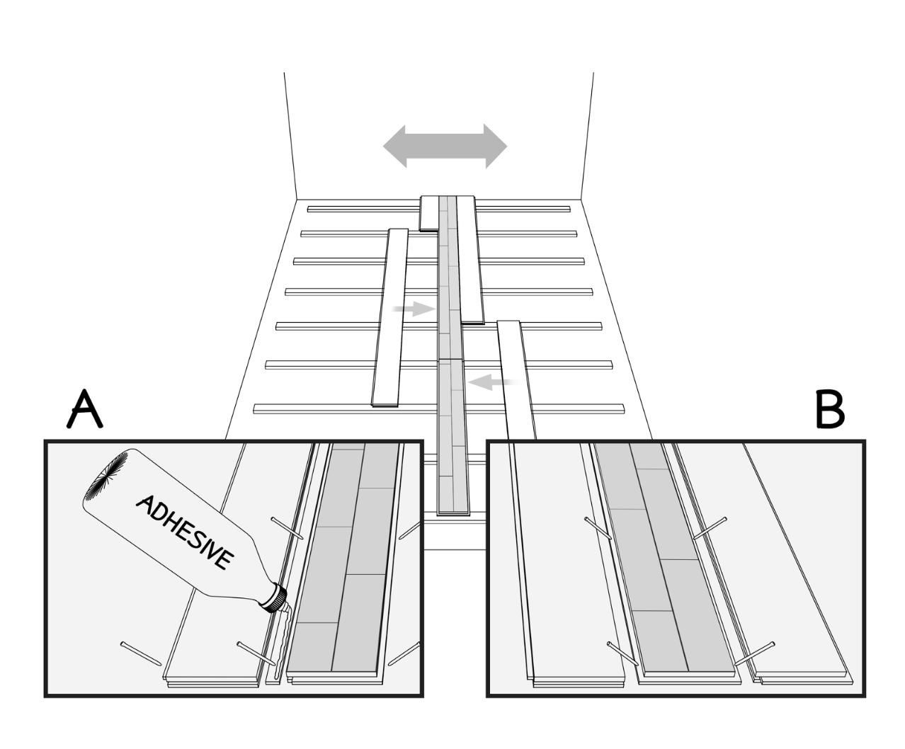
2.3 SUBCONSTRUCTION
The battens are laid parallel to the shortest side of the room to ensure that the floorboards are laid parallel to the longest side of the room.
The first and last rows of battens are spaced with a distance of 100 mm from the wall to the centre of the batten. The second batten row is spaced at 266 mm centres to the first batten row.
All other batten rows are spaced at 336.4 mm centres by using the Spacing Battens (A).
Batten end joints should not be in line, but must be staggered min. 600 mm from the neighboring row.
Squash:
If the floor is used as a squash court permanent spacing blocks spaced at 500 mm centres are attached between the first batten row and the end wall where the play is performed.

2.4 BATTENS AT NET POSTS, PIPES ETC.
Place extra loose battens at net posts, pipes, etc. Loose battens must be elastic.
Distance to all walls, net posts, pipes, etc. see section 2.2.
2.5 LAYING OF FLOORBOARDS
If the floor is more than 12 m wide the installation must begin in the middle of the sports hall. Use one of the following two methods:
- The two centre floorboards are joined with a loose tongue which must be glued to one of the floorboards in the full length of the floorboard.
- Use Junckers CenterRow boards. These floorboards are constructed with a tongue on both sides.
The floorboards are laid in a continuous pattern with well-defined distribution of floorboard header joints from row to row of 4 x the batten centres, i.e.1345.6 mm. In that way that all floorboard headerjoints are supported. The floorboards are secretly nailed, see section 2.7

2.6 DISTANCE, BOARD HEADER JOINTS
The distance between board header joints in two consecutive rows must be 4 x 336.4 mm = 1345.6 mm, as shown in the drawing.

2.7 NAILING
Use Junckers machine J-Nails, 2.2 x 45 mm. The floorboards are secretly nailed at an angle of 45°. Do not nail closer than 50 mm to stave joints and never in the floorboard end joints.
To avoid creaking, the floorboards are pressed down on the battens while they are nailed.
The distance between the floorboards and walls/vertical fixed installations is calculated as 1.5 mm per running metre of floor width on each side, and at end walls 1 mm per running metre of floor length, with an overall distance of minimum 30 mm.
The first and last rows of floorboards installed must be face nailed or screwed and then covered with matching filler.
TO AVOID STRESS AND GAPS, REMEMBER DURING THE INSTALLATION TO WATCH THE FIXED 10-BOARD MEASUREMENT.
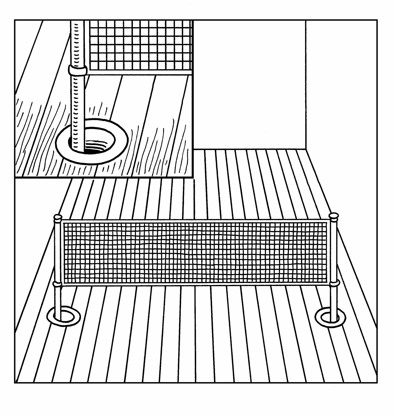
2.8 BUSHINGS
On mounting of bushings in the surface of the floor the internal diameter of the bushing must exceed that of the pipe, i.e. the external diameter of the net pole, by at least 40 mm.
At the outermost zones of the floor all bushings are mounted eccentrically towards the middle of the floor in relation to the sockets in the concrete.
Floor rosettes must be mounted to allow both vertical and horizontal movement of the floor to take place unimpeded.

2.9 COMBI SPORTS SKIRTING
Junckers Combi Sports skirting can depending on the wanted cover width be mounted upright or in a lying position, see figure.
The foot of the skirting must lie flat and be in contact with the floor. End joints may be either butt jointed together or cut as a 45° mitre joint to enhance the visual effect of the joint.
The skirting can be either glue fixed to the walls or screw fixed.
Do not fix the skirting to the floor and ensure that the skirting is not exerting any downward pressure on the floor.