BATTEN FLOORS
SPECIFIER´S AND INSTALLATION INSTRUCTIONS
C 1.2
1.0 SPECIFIER'S INSTRUCTIONS
INFORMATION, BATTEN FLOORS
|
C 1.0 |
General information |
|
C 1.2 |
Specifier's and |
Table 1
1.1 SYSTEM SPECIFICATIONS
These instructions describe the general conditions for specification and installation of Junckers Batten floors for residential and commercial buildings.
A Junckers Batten floor is a load-bearing system in which 22 mm (7/8") solid hardwood 2-strip or 20.5 mm (3/4") plank floorboards are nailed to joists or battens levelled up on a firm subfloor. These instructions also describe nailing of hardwood floorboards to load-bearing wooden subfloors such as softwood floorboards or plywood.
The floor system can be installed in combination with underfloor heating, see datasheet E 4.2. for further information. Please note that full information on a floor system comprises General information and Specifier's and Installation instructions, see table 1.
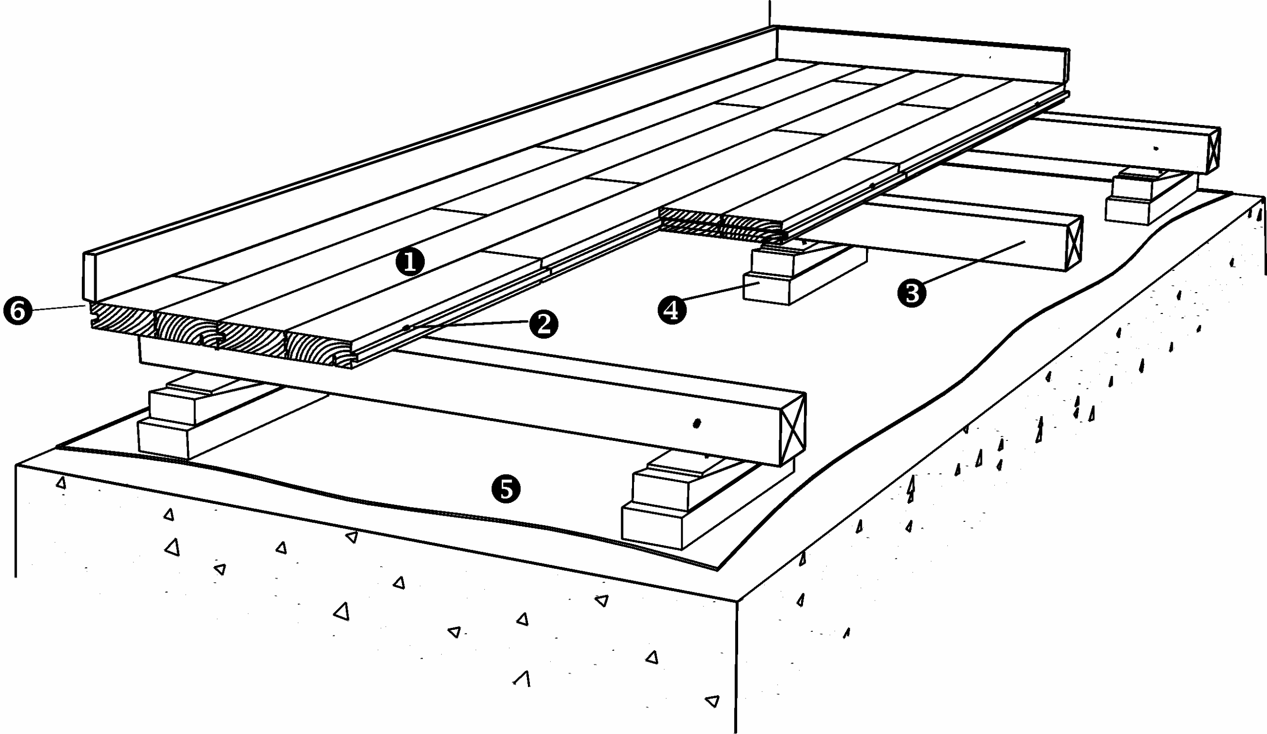
1.2 FLOOR COMPONENTS
- Junckers 2-strip or plank floor
Wood species, dimensions, grades and finish:
2-strip: see data sheet B 2.0
Planks: see data sheet B 5.0 - Nails
- Battens or joists
- Packing,
Soft packing, Plywood, Plastic wedges - Sylvathene Moisture barrier, 0.2 mm PE-foil
- Expansion gap at the wall
1.5 mm (¹/₁₆") per m width on each side and 1 mm (³/₆₄") per m length at each end.
All gaps should be a min. size of 12 mm (1/2") (UK: min. 15 mm).
Is also required at fixed points, e.g. columns.
Fig. 1
1.3 NAILING TO BATTENS AND JOISTS
Only 22 mm (7/8") and 20.5 mm (3/4") floorboards can be nailed to battens and joists.
Nailing to battens: Use Plain battens in a dimension of minimum 38 x 56 mm (1 ¹/₂" x 2 ¹³/₆₄") or laminated battens in a dimension of minimum 39 x 40 mm (1 ¹⁷/₃₂" x 1 ³⁷/₆₄").
Nailing to joists: The joist system consists of whole timbers (square or approximated square cross-sections) of minimum 100 x 100 mm (3 ¹⁵/₁₆" x 3 ¹⁵/₁₆"), half timbers or laminated timbers, and is used above ventilation spaces and cellars or as floor structures.
See Installation instructions section 1.7 for requirements of nails.
1.4 NAILING TO LOAD BEARING WOODEN SUBFLOORS
All thicknesses of floorboards can be nailed to load bearing subfloors of plywood or floorboards.
The best result is achieved by nailing through the subfloor into the battens or joists. As intermediate layer use floor cardboard, 500 g/m².
The subfloor itself must be of adequate stiffness and be flat according to requirements described in section 1.5.
See Installation instructions section 1.7 and 1.9 for requirements of nails.
1.5 LEVELNESS OF BATTENS, JOISTS AND SUBFLOOR
Battens, joists and subfloor must be straight with no distortion.
After installation the top surface of the battens, joists and subfloor must deviate maximum 2 mm (⁵/₆₄") from flat level under a 1.5 m straight edge (UK: 3 mm under a 2 m straight edge), both across and along the individual battens or joists.
With joists this can be achieved by mounting strip ledges or firing pieces.
1.6 MOISTURE CONTENT IN BATTENS AND JOISTS
Joists and battens must be made of pine or spruce. The moisture content must be within the range of 6-12 % and no individual measurement must be larger than 12 %. The moisture content is therefore expressed as max. 12 %.
Any impregnation fluid used on battens or joists must be dry before the floor is installed. Battens must be of a well-selected wood quality. Joists must also be of a well-selected wood quality and stress graded.
For joists deeper than 100 mm (3 ¹⁵/₁₆") the recommended moisture content should not fluctuate more than 2 % from the measured mean moisture content, in order to avoid problems of uneven shrinkage of joists, resulting in creaking floors.
1.7 SPACING OF BATTENS AND JOISTS
Spacing of battens or joists is determined according to the use of and expected load on the floor. Table 2 presents batten and joist spacing normally used for 22 mm 2-strip floorboards.
| TABLE 2 | Batten and joist spacing, 22 mm (7/8") 2-strip floor boards | ||
|
Loading categories |
Middle battens |
First and last battens |
Remarks |
|
A+B |
800 mm (31 ¹/₂") |
550 mm (21 ²¹/₃₂") |
Only for joists min. 125x125 mm(4 15/16″ × 4 15/16″). |
|
C1 + C2 |
500 mm (19 ¹¹/₁₆") |
400 mm (15 ³/₄") |
If deflection critirion for wheel load should be complied with. |
|
C3 + D1 |
411 mm (16 ³/₁₆"!) |
350 mm (13 ²⁵/₃₂") |
For board length 3700 mm (12′) |
Table 3 presents batten and joist spacing normally used for 20.5 mm (3/4") Planks:
| TABLE 3 | Batten and joist spacing for 20.5 mm (3/4") Planks | ||
|
Loading categories |
Middle battens |
First and last battens |
Remarks |
|
A+B |
500 mm (19 ¹¹/₁₆") |
400 mm (15 ³/₄") |
Standard batten centres. |
|
C1+C2+C3+D1 |
400 mm (15 ³/₄") |
350 mm (13 ²⁵/₃₂") |
Max. batten centres. Adjust batten centres to support all header joints. |
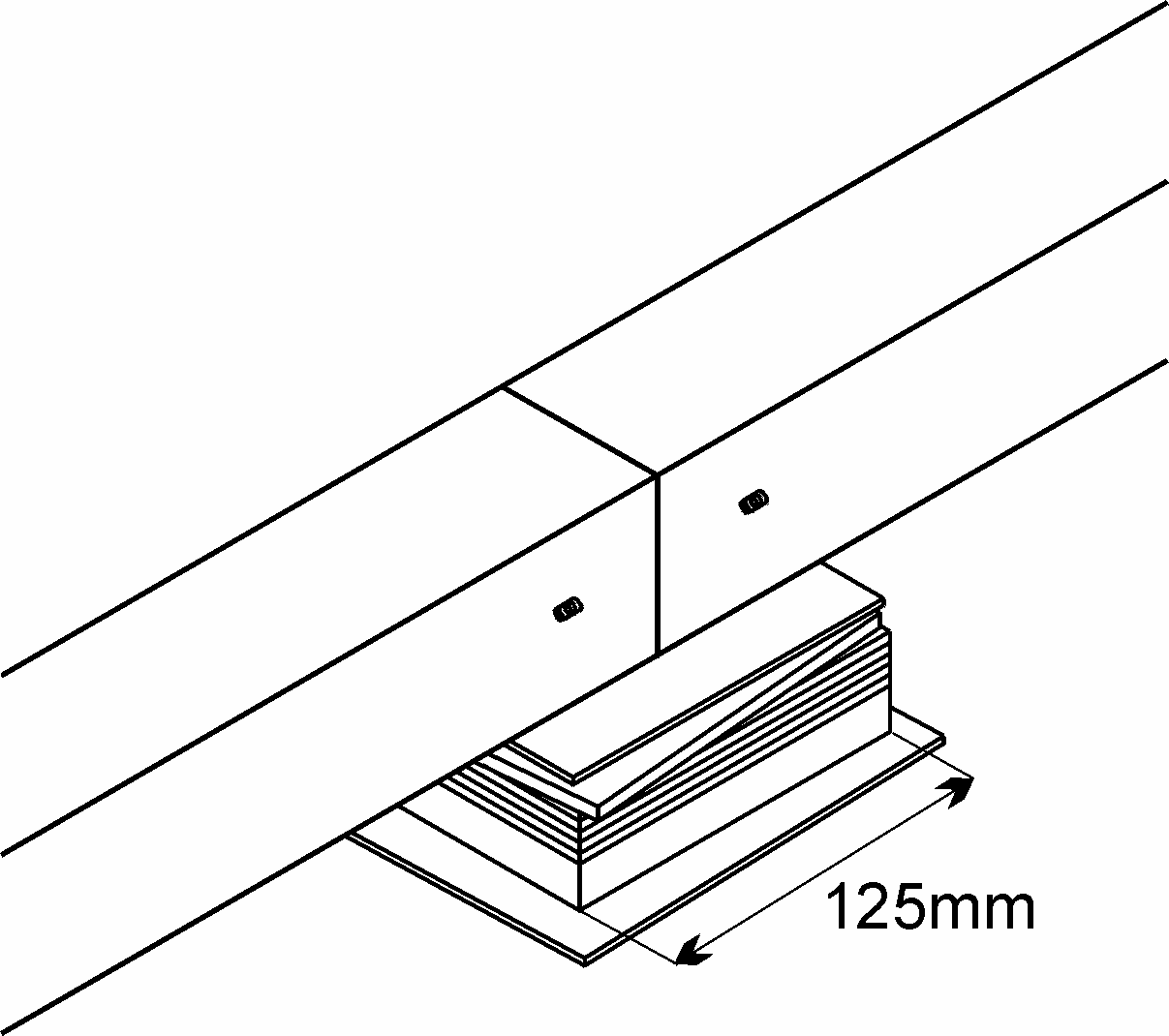
Fig. 2
1.8 PACKINGS
The packing used for battens must be of a hard and dimensionally stable material such as plywood, combined with a soft board material, e.g. soft fibre-boards. Alternatively, plastic wedges may be used, either alone or in combination with the aforementioned materials.
If soft packing is used it is placed at the bottom of the packing: Soft packing is made of 12–13 mm (1/2″) thick soft 100 cm² (15 1/2 in²) fibreboards, e.g. 125 × 80 mm (4 15/16″ × 3 1/8″), with a density of 225–300 kg/m³ (ca. 14–19 lb/ft³), glued to at least 12 mm (1/2″) thick plywood.
The packing is fixed to the battens with nails which should never reach down into the soft material or touch the concrete. If the packing is exclusively of soft material, it should be glued to the battens.
Batten joints may be supported by one single packing piece if the packing in the batten direction has a length of at least 125 mm (4 15/16″), see Fig. 2. Batten joints must be staggered at least 600 mm (23 ⁵/₈") to each other. These may only occur in straight lines where the batten ends are securely plate fixed together. At walls, etc. packing is placed a maximum distance of 100 mm (3 ¹⁵/₁₆") from the batten ends.
On unscreeded concrete surfaces bitumen based felt under the packing is recommended. Using felt ensures that the packing is firmly placed and the felt also reinforces the moisture barrier, preventing moisture from seeping up into the packing material, which is exposed to a heavy load on unscreeded concrete.
Fig. 3
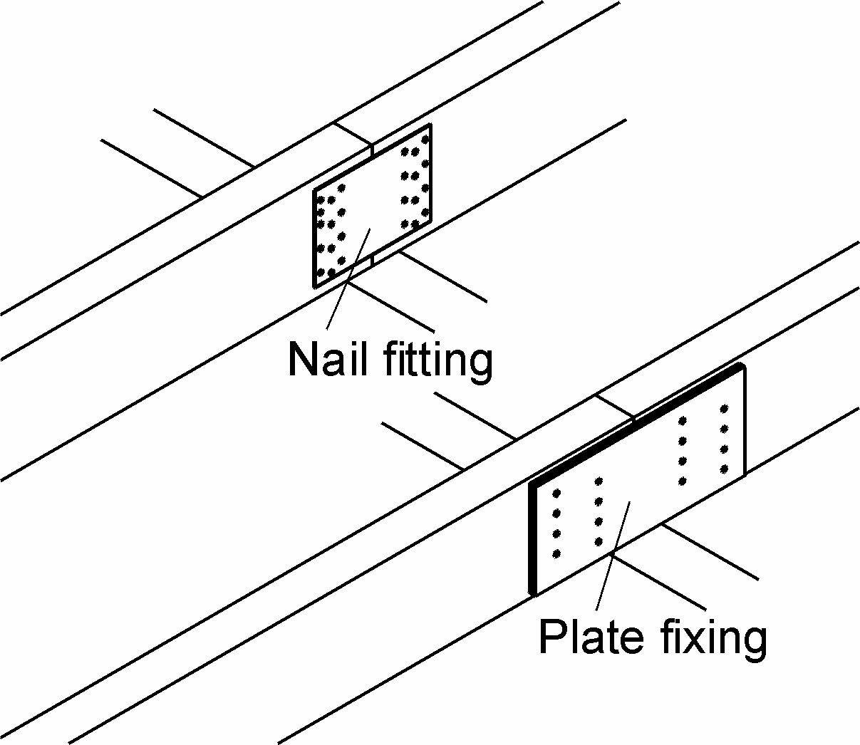
Packing material for joists must be of hard and inelastic material, since the load is usually high. Where joists are laid against pillars, etc. a robust moisture barrier, e.g. bitumen based felt, must be placed at the bottom.
Joints between two joists must always be across a supporting structure and the two joist ends must be joined mechanically using plates or nail fittings, see Fig. 3.
Fig. 4
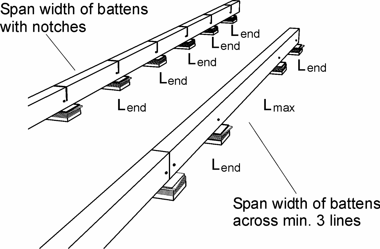
1.9 SPACING OF PACKINGS
Recommended maximum packing centres for selected batten dimensions in different load classes, see Table 4.
At the end of all battens, at joints between battens and on battens with notches the span width Lend is used, see Fig. 4.
Other packing pieces are spaced as Lmax but to a minimum number of three pieces, see Dimentioning assumptions for spacing of packing.
DIMENSIONING ASSUMPTIONS FOR SPACING OF PACKING
Moisture class: Internal
Wood quality: Well-selected
Static system:
Battens continuous across at least 3 bays (Lmax).
At the end line the packing distance is reduced equivalent to simple support (Lend).
|
TABLE 4 |
Maximum packing centres |
|||
|
Batten sizes mm |
Residential (a),commercial |
Public buildings (C1, C2, C3) |
||
|
width x height |
Lmax mm |
Lend mm |
Lmax mm |
Lend mm |
|
40 x 39 (1.57" x 1.54"), laminated |
550 (21.65") |
500 (19.69") |
440 (17.32") |
400 (15.75") |
Information on load classes, see C 1.0 - Table 1.
Criterion for deflection in connection with spacing of battens and joists
Deflection U (mm) max.:
U <L/700 for useful load q (kN/m2)
U < L/200 for useful load Q (kN)
U < 2.5 mm (0.10") (Spacing of battens and joists, L (mm))
For further definition of load classes and types: see C 1.0, Stiffness and loadbearing strength.
1.10 STIFFNESS AND LOADBEARING STRENGTH
The stiffness and loadbearing strength of batten and joist structures depend on the type of load and load area, the spacing of battens and joists and the bond pattern of boards, including any support of board ends.
Table 5 presents the stiffness and loadbearing strength in relation to load classes.
|
TABLE 5 |
Loading types |
|
|
Loading category |
Area- and Point load |
Wheel load |
|
A+B: Residential + office |
Approved |
- |
Fig. 5
1.11 THE 10-BOARD RULE, AVOID STRESS AND GAPS
In order to minimize stress or gaps in the floor due to fluctuations in the climatic conditions within the building, floorboards must be laid according to a 10‑board rule.
This indicates the measurement across 10 floorboards when laid and should be checked continuously during the installation and afterwards, see Fig. 5.
To keep the 10-board measurement (10 BM), it is recommended to use Junckers temporary spacers during installation of the floor. Spacers are delivered in a range of sizes to suit the expected relative humidity of the room.
Fig. 6
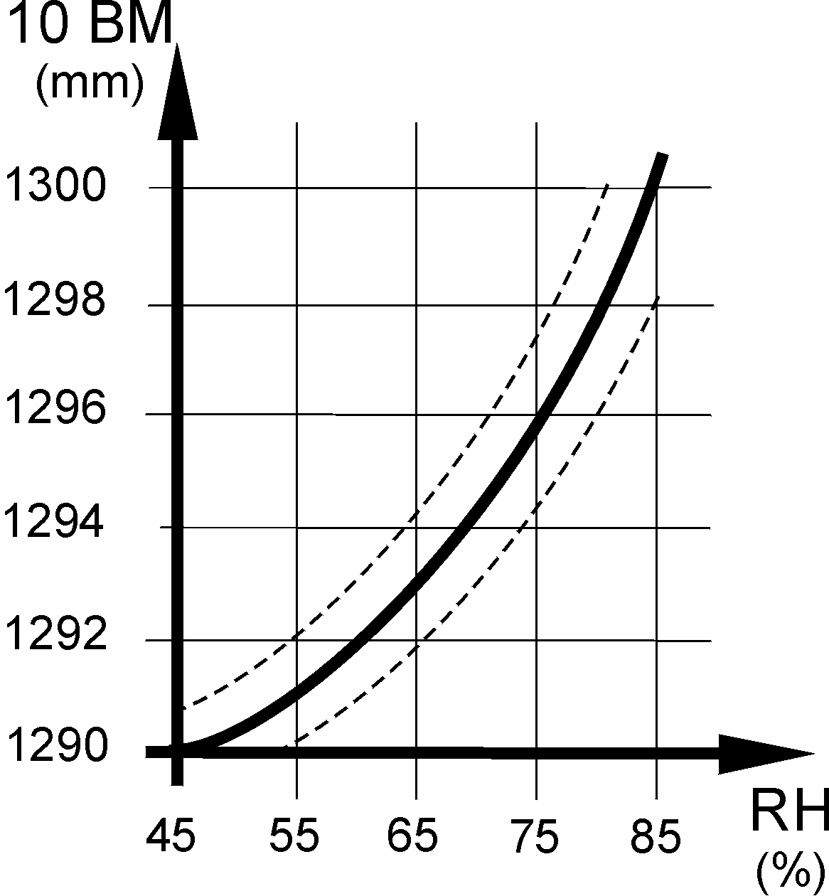
The 10-board measurement is chosen on the basis of the expected maximum relative humidity in the building when in use throughout the year, see fig. 6
The graph in fig. 6 illustrates the 10-board rule in relation to the relative air humidity for 129 mm (5") floorboards. E.g. an expected relative humidity of max. 65 % RH will normally require a 10- board measurement of approx. 1294 mm (50 15/16").
The outer limits of the 10-board measurement, which also depend on the floor size and product type, are marked with dotted lines. The size of the floor area, as well as it’s location, i.e. ground floor or horizontal division, may also have influence on the choice of the 10-board measurement.
Table 6 states the 10-board measurent for different floorboard widths at a relative humidity between 35-65 %. The measurement must continuously be checked during installation.
|
TABLE 6 |
10-board measurement |
||
|
Construction |
22x129 mm 2-strip |
20.5x140 mm plank |
20,5x185 mm plank |
|
Concrete upper floor: |
1292 mm (50.87") |
1404 mm (55.28") |
1854 mm (72.99") |
*For ship’s decking the 10-board measurement corresponds to a slightly compression of the neoprene strip during installation.
Fig. 7
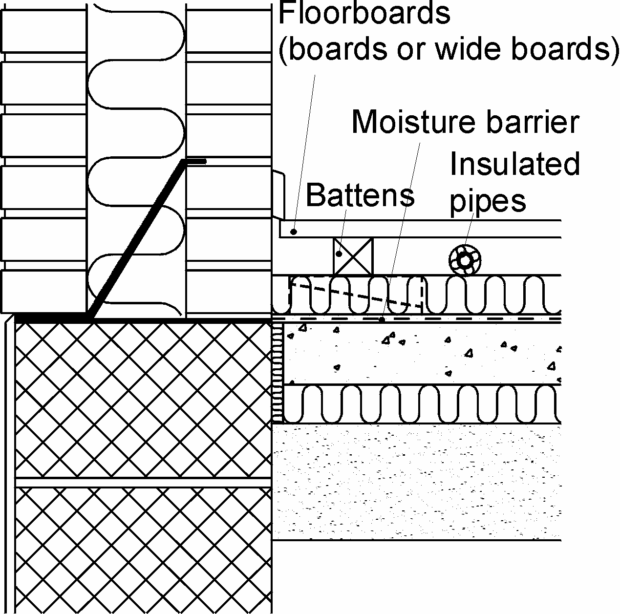
1.12 THERMAL INSULATION
Batten and joist structures provide good opportunities to incorporate thermal insulation. Generally, thermal insulation should be incorporated directly over boiler rooms.
All central heating, cold and hot water pipes under floors must be carefully insulated using at least 20 mm (4/5") mineral wool or similar.
As a rule a minimum 10 mm (2/5) air cavity should be present between the underside of boards and pipe insulation, see Fig. 7.
1.13 MOISTURE PROTECTION
At ground level and in floor structures subject to a risk of moisture, a protection against dampness from both residual and ground moisture is required. A moisture barrier is established by laying a damp-proof membrane, Junckers 0.20 mm (8 mil) Sylvathene or 1000 g polythene directly on the concrete before laying out the battens, see Fig. 7.
The residual moisture contained in the concrete or screed should not exceed 90 % RH (UK: Concrete moisture max. 75 % RH acc. to BS 8201, when checked by measurement). If the residual moisture is above 75 % RH (UK: Concrete moisture max. 75 % RH allowed, see above), all overlaps must be taped using 50 mm (2") wide tape.
Where the batten system is mounted on upper floor structures of reinforced concrete etc., a separate moisture barrier may not be required, provided that the floor is completely dry (max. 50% RH checked by measurement). Above wet rooms or archway structures or unheated rooms, a moisture membrane of a 0.20 mm PE membrane is laid directly on the concrete.
Fig. 8
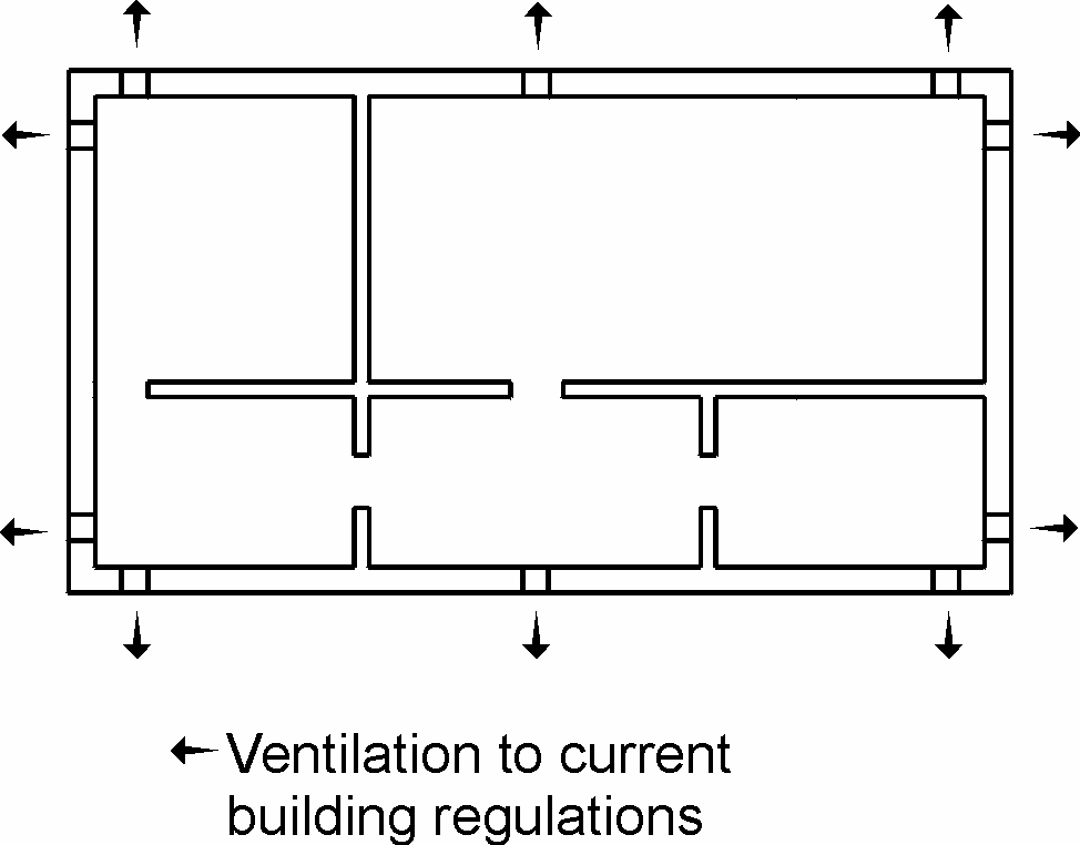
On joists across ventilation spaces a damp-proof membrane is laid, e.g. Junckers 0.20 mm Sylvathene or 1000 g polythene. As a general rule the membrane is placed across the insulation, i.e. on the joists immediately below the boards, provided that the ventilation space is effectively ventilated to the outdoors and that the underside of the construction is open to diffusion, so as to eliminate the risk of fungal attacks in the joists, see Fig. 8.
In special cases, e.g. in holiday homes, heating and insulation conditions can be vital to the functioning of the damp-proof membrane, requiring it to be placed in a different way to that described above. In such situations it is advisable to request the assistance of Junckers Technical Service Department.
1.14 STEP SOUND REDUCTION, HEAVY DIVISIONS
22 or 20.5 mm (7/8" or 3/4") floorboards on 45 x 45 mm (1 3/4" x 1 3/4") battens with soft packings: 19 dB.
22 or 20.5 mm (7/8" or 3/4") floorboards on 45 x 45 mm (1 3/4" x 1 3/4") battens with plastic wedges: 17-19 dB.
For general information about sound and practical guidelines on acoustics in floor constructions, see E 5.0.
1.15 CONSUMPTION OF MATERIALS
Floorboards: Floor area + approx. 2 % wastage
Nails: Approx. 15 pcs. per m² (depending on batten centres and floorboard width)
Junckers Sylvathene moisture barrier,: Floor area + 25 % extra for overlap + wastage
Battens: e.g. 39 x 40 mm (0.35" × 1.57") :
c/c 600 mm (23 ⅝") : approx. 2 lin. m per m²
c/c 500 mm (19 ¾") : approx. 2.4 lin. m per m²
Packings:
c/c 600 mm (23 ⅝") : approx. 4 pcs. per m²
c/c 500 mm (19 ¾") : approx. 4.5 pcs. per m²
2.0 INSTALLATION INSTRUCTIONS
BEFORE BEGINNING TO INSTALL THE FLOOR
The building must be weather tight. The heating system must be installed and tested and during the heating season should be in operation. Cast concrete elements, screeding and other wet trades, which contribute moisture to the building, e.g. tiling, plastering and priming of paintwork, must also be completed.
The relative humidity in the building must be between 35-65 % RH and the temperature approx. 20 °C. The residual moisture contained in the concrete or screed must not exceed 85 % RH (UK: Concrete moisture max. 75 % RH acc. to BS 8201, when checked by measurement). In wooden based subfloors, as well as in battens, the moisture content should not exceed 12 %.
Solid floorboards should always be laid immediately on their arrival at the building. The packing on the bundles must not be removed until just prior to laying the floor, i.e. no acclimatising of the boards on site must take place. In case of doubt please contact your Junckers distributor before installing the floor.
2.1 MOISTURE BARRIER
Minimum 0.20 mm polythene membrane is laid on all concrete or screeded bases, Eg. Junckers Sylvathene. The moisture barrier is laid with an overlap of 200 mm (7 ⅞") at all joints. It must be placed under heating pipes and turned well up at walls, etc.
If the residual moisture is above 75 % RH, all overlaps must be taped using 50 mm (2") wide tape.
2.2 ESTABLISH BATTEN DISTANCE
Battens must be dry, straight and without bowing or twisting. Battens must be spaced at correct intervals. The batten centres, B and C, are determined according to the use of the floor, the expected loads and type of floor (20.5 mm (3/4") Plank or 22 mm (7/8") 2-strip):
Residential buildings:
20.5 mm (3/4") Planks: B = 500 (19.69") and C = 400 mm (15.75").
22 mm (7/8") 2-strip boards: B = 600 (23.62") and C 500 mm (19.69").
Distance (D) from wall to first batten max. 80 mm (3"). Batten end joints must be staggered (A) minimum 600 mm (23.62") from the neighbouring row and must only be in a line if well connected together. Distance from batten ends to walls must be minimum 10 mm (3/8").
In commercial buildings the batten centres must be reduced according to the stipulated load class, see C 1.0, Load classes and Specifers instructions section 7, table 2 and 3.
2.3 BATTENS THROUGH DOORWAYS AND AT PIPES
If laying through doorways or similar always use at least 3 battens projecting through doorways.
Hot as well as cold water pipes must be insulated with minimum 20 mm (13/16″) insulation or similar
Centre distance (A) is used in middle batten areas and centre distance (B) at batten end joints, saw cuts and at batten ends. Batten end joints must be supported by unbroken packing material.
At walls, etc. the distance (C) from batten ends to the centre of the first packing must be maximum 80 mm (3.15").
2.4 LEVELLING OF BATTENS
Battens are levelled to a flatness tolerance of 2 mm under a 1.5 m straight edge (UK: 3 mm under a 2 m straight edge).
The table below shows examples of required centre distance between packing material according to batten dimensions and the use of the floor in commercial and residential buildings. See Specifier´s instructions section 9 for other packing distances in relation to batten distance.
|
Battens |
Residential |
Commercial |
||
|
Width x hight (mm) |
A |
B |
A |
B |
|
40 x 39 (1.57" x 1.54") laminated |
550 (21.65") |
500 (19.69") |
440 (17.32") |
400 (15.75") |
2.5 PACKING MATERIAL
Packing material must be dimensionally stable. All packing materials must be securely fixed to the battens.
If a suitable fibreboard material is used for step sound reduction it must be glued under load distributing plywood packing. Nails for fixing of packing material must not reach down into the fibreboard or touch the concrete base.
At notches in battens, additional packing must be used as close as possible to each side of the cut.
2.6 LAYING OUT FLOORBOARDS
Lay the floorboards in a random joint pattern. Distribute the header joints as far apart as possible. However, the distance between floorboard joints in two successive rows should be at least 250 mm (13/16″). Board end joints may occur in between battens but no more than for every third board.
Stave joints in one row of floorboards should not be in line with stave joints in a neighbouring row, but must be spread as far as possible (min. 50 mm (2"). Cut the last row of boards to form the correct size of expansion gaps at the wall (A).
Expansion gaps to walls and fixed installations must be 1.5 mm per running metre of floor width on each side (A), and 1.0 mm per running metre of floor length at each end (B), all with a minimum size of 12 mm (1/2") (UK: 15 mm).
For floors over 12 m (39'4'') wide it is recommended to start from the centre using a loose tongue to join the central boards together.
Requirements of nails/screws:
- Junckers J-Nails, 2.2 x 65 mm (0.09" × (2 9/16")
type-T machine nails
- 2.6 x 65 mm (0.10" × (2 9/16") T-nails (machine nails)
- 2.8 x 65 mm (0.11" × (2 9/16″) lost-head wire nails
- 4.2 x 45 mm (0.17" × 1 3/4"") screws
2.7 NAILING
Nailing of floorboards must be conducted according to the 10-board rule as described in the Specifier´s instructions, section 11. Remember that the 10-board measurement must be checked continuously during the installation and afterwards.
The floorboards are secret nailed at a 45° angle with one nail in each floorboard, into each batten/joist.
- To ensure that the nail has the necessary shearing strength, it is important to adhere to Junckers’ requirements for machine nails.
- Nailing in full square timber such as 100 x 100 mm (3 15/16″ × 3 15/16″") must be in the outermost third of the joist, so that wire nails do not make contact with any shrinkage cracks in the middle of the joist.
- When nailing by hand, pre-drill with a 2-2.5 mm (0.08–0.10") drill.
- Alternatively, 4.2 x 45 mm (0.17" × 1 3/4"") screws (UK: 45 x no. 4 screws) can be used after pre-drilling using a 3-4 mm (0.12–0.16") drill.
- Do not nail any closer than 50 mm (2") from a board- or stave end.
2.8 PIPES, DOOR FRAMES, THRESHOLDS
Around pipes, drill a hole in the floorboard to accommodate the pipe. The space around the pipe must be the same as the expansion gap at the wall. A tapered wedge is cut out, so that it can be glued in place. This gap is covered using a radiator pipe cover.
At door frames and architrave’s, cut the base of the frame and architrave to allow the floor to fit underneath.
At the threshold the expansion gap can be covered by a threshold strip or, if levels reduce, fit a ramp.
2.9 LAYING ON EXISTING WOODEN FLOORS
Alternatively the floorboards can be nailed to a subfloor such as plywood, existing floorboards etc. (caution with chipboard) The subfloor must be sufficiently rigid, flat, level and dry. To avoid creaking, fasten the wooden subfloor securely and use floor felt, 500 g/m2, as an intermediate layer.
Nail according to following guidelines:
14 (9/16") and 15 mm (5/8") floorboards:
Use 1.8 × 38 mm (0.07″ × 1 1/2″) T-nails (machine nails) or 1.8 × 40 mm (0.07″ × 1 9/16″) lost-head wire nails.
Nail centres: maximum 450 mm (17 3/4″).
20.5 (3/4") and 22 mm (7/8") floorboards:
Preferably nailing must be done in a line across existing battens/joists.
If the batten/joist distance exceeds 600 mm (23 5/8″"), then nail directly into the subfloor with a distance of max. 450 mm (17 3/4″").
Nail/screw types: See section 2.7.
Pattern and distances as described in section 2.6.