GLUED HARDWOOD FLOORS
SPECIFIER´S AND INSTALLATION INSTRUCTIONS
C 1.3
C 1.3
1.0 SPECIFIER'S INSTRUCTIONS
INFORMATION GLUED FLOORS
|
C 1.0 |
General information |
|
C 1.3 |
Specifier's and |
Table 1
1.1 SYSTEM SPECIFICATIONS
These instructions describe how to fully glue
- 14 (9/16”) and 22 mm (7/8'') 2-strip solid hardwood floorboards
- 15 (3/4'') and 20.5 mm (3/4'') solid hardwood planks
to a dry, loadbearing subfloor of concrete, lightweight concrete, screed or wooden material.
Gluing of floors can be conducted in residential and commercial areas.
Gluing of Junckers solid hardwood floors can be done in combination with underfloor heating systems. For more information see E 4.3.
Please note that full information on a floor system comprises General information and Specifier's and Installation instructions, see table 1.
1.2 FLOOR COMPONENTS
- Junckers 2-strip or plank floor
Wood species, dimensions, grades and finish:
2-strip: see B 2.0
Planks: see B 5.0 - Adhesive and moisture barrier
Junckers Parquet Glue
Junckers SMP Liquid Moisture Barrier 1.0 (if required) - Expansion gap at the wall
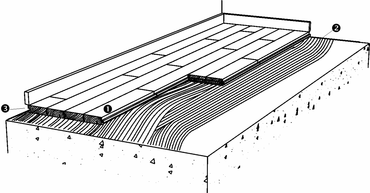
1.5 mm per m of floor width on each side and 1 mm per m length at each end. All gaps should be a min. size of 12 mm (1/2'') (UK: min. 15 mm). Is also required at fixed points, e.g. columns.
Fig. 1
1.3 LOADBEARING STRENGTH
The loadbearing strength of the floor system depends on the type of load. Table 2 presents loadbearing strength in accordance with the load classes. For further definition of load classes and types, see General information C 1.0
|
Table 2 |
Loading types |
|
|
Loading category |
Area- and Point load |
Wheel load |
|
A+B: Residential + Office |
Approved (all products) |
Approved (all products) |
|
C1 + C2 + C3 + D1: Public buildings and shoppings areas |
Approved (all products) |
Approved (all products) |
1.4 SUBFLOORS & PROTECTION AGAINST RESIDUAL MOISTURE
Subfloors can be made of concrete, lightweight concrete, screed or wooden materials.
If several types of subfloors make up the same floor area, the subfloors must be of uniform elasticity and flatness to ensure that the final flooring is of a consistent nature.
Wood:
Wooden subfloors of chipboard, plywood or floorboards mounted on battens or a frame of joists must be of sufficient inherent elasticity with a bearing strength which is adequate for the use of and expected load on the floor. The moisture content of wooden subfloors must be in balance with the relative humidity of the room, i.e. 6-12 % moisture content.
On wood-based subfloors with a risk of moisture penetration, e.g. above crawl spaces, etc., effective ventilation of the subfloor must be ensured, and that the underside of the structure is open to diffusion.
Concrete:
When glueing hardwood floors it is not possible to use a conventional damp-proof membrane. It is therefore very important to ensure that the surface of the subfloor is smooth, clean and dry. The residual moisture in the subfloor must thus not exceed 65 % RH, which must be checked by measuring, see section 11 "Measurement of moisture in subfloors".
If the concrete subfloor has a moisture content between 65-95 % RH, or in case of underfloor heating, apply Junckers SMP Liquid Moisture Barrier 1.0 before gluing, see directions for use in H 6.6.
1.5 THE SURFACE OF THE SUBFLOOR
The surface of the subfloor must be smooth and clean, i.e. any slurry, etc. must be removed. The adhesion of the adhesive may be compromised, as the slurry surface may not be strong enough to cope with the elasticity of the adhesive when the floorboards expand throughout the year.
The subfloor needs to have a minimum strength of 1,5 MPa.
To ensure smooth absorption and improved adhesion, as well as to strengthen abraded concrete edges and existing adhesive residues, we recommend that you use Junckers SMP Liquid Moisture Barrier 1.0 as a primer on strongly absorbent subfloors, see H 6.5.
1.6 BEFORE BEGINNING TO INSTALL THE FLOOR
The building must be weather tight. The heating system must be installed, tested and should during the heating season be in operation. Cast concrete elements, screeding and other wet trades, which contribute moisture to the building, e.g. tiling, plastering and priming of paintwork, must also be completed.
The relative humidity in the building must be between 35-65 % RH and the temperature approx. 20 °C (68° F).
Solid floorboards should always be laid immediately after arrival to the site. Wrapping of the packages must not be removed until just prior to laying the floor, i.e. no acclimatising of the floorboards on site must take place.
1.7 ADHESIVE AND APPLICATION TOOLS
For gluing of the floorboards Junckers Parquet Glue must be used. The adhesive is applied by using Junckers spatulas, see Installation instructions, section 2.2 Applying adhesive.
Fig. 2
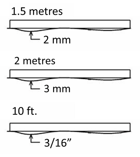
1.8 FLATNESS OF THE SUB FLOOR
The subfloor must be levelled so that any deviations in the flatness do not conflict with the requirements of the method stated below.
Straight edge:
The subfloor must be flat with a maximum deviation of 2 mm under a 1.5 m straight edge.
(UK: 3 mm under a 2 m straight edge).
(US: 3/16” under a 10 ft. straight edge).
Deviations are measured as gaps under the straight edge. The surface must be smooth. Any irregularities must be corrected by grinding or by using a self levelling compound.
Fig. 3
1.9 THE 10-BOARD RULE
In order to minimize stress or gaps in the floor due to fluctuations in the climatic conditions within the building, floorboards must be laid according to a 10‑board rule.
This indicates the measurement across 10 floorboards when laid and should be checked continuously during the installation and afterwards, see Fig. 3.
To keep the 10-board measurement (10 BM), it is recommended to use Junckers temporary spacers during installation of the floor. Spacers are delivered in a range of sizes to suit the expected relative humidity of the room.
Fig. 4
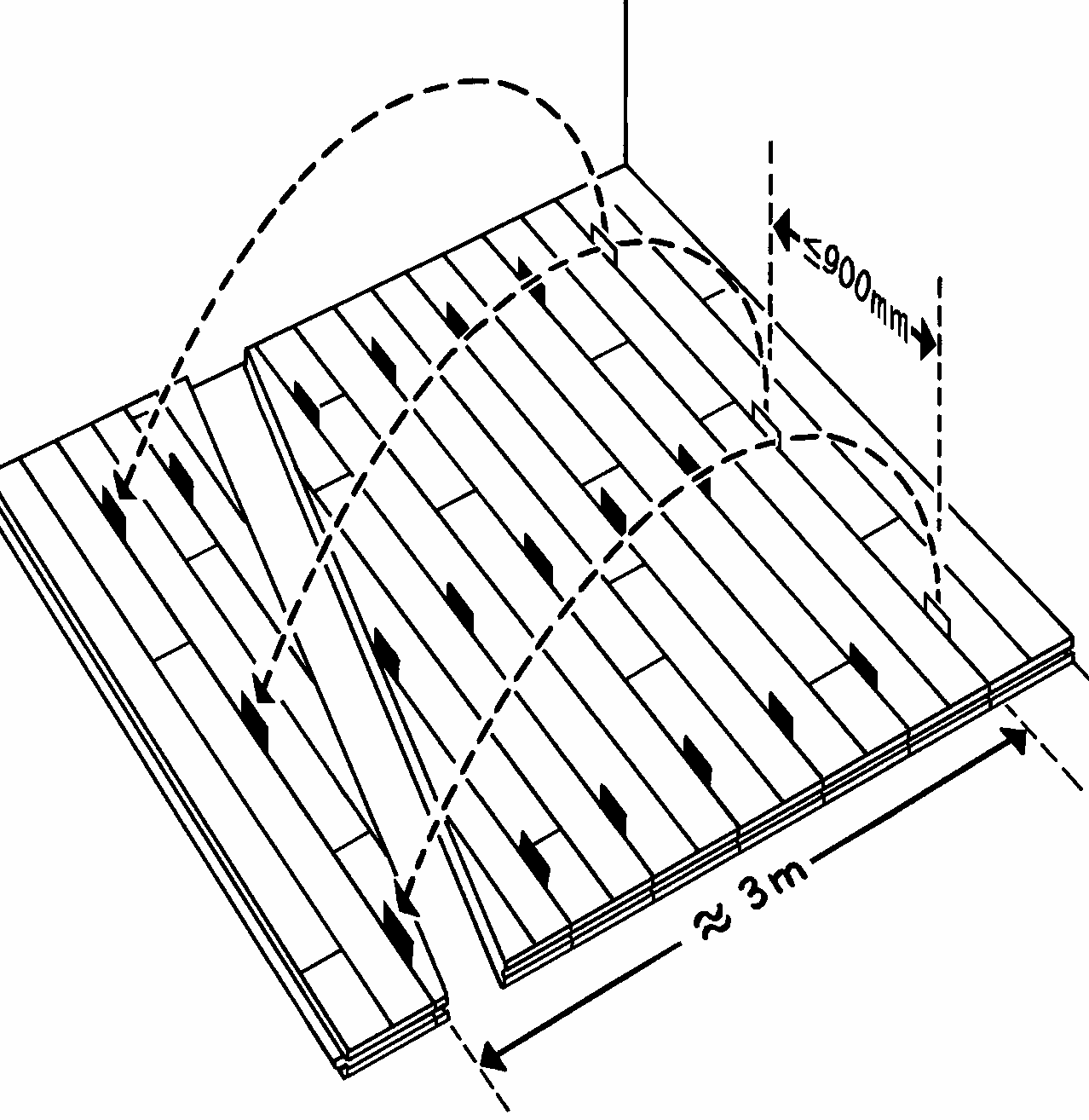
Consumption of spacers: Spacers are used at max. 900 mm (35 7/16") between all flooboard-rows up to 3 m (9′ 10 1/8″) back in the laying direction. This gives a consumption of approx. 25 spacers per metre (3' 3'') of floor, calculated in the lengthwise direction of the floorboards.
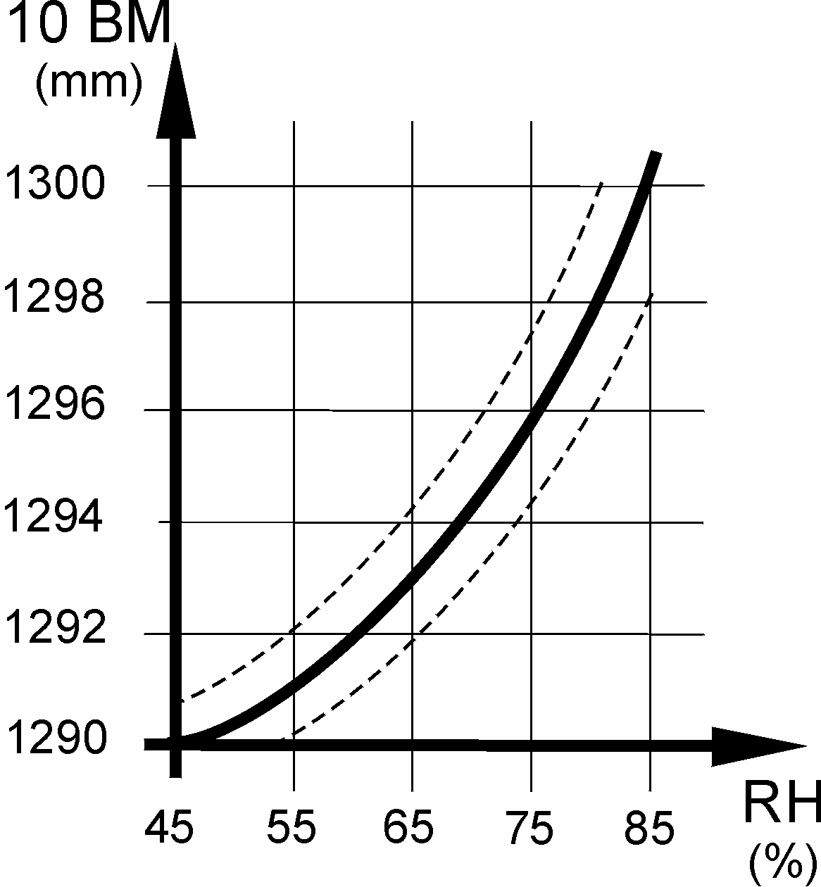
The 10-board measurement is chosen on the basis of the expected maximum relative humidity in the building when in use throughout the year, see fig. 4
The graph in fig. 4 illustrates the 10-board rule in relation to the relative air humidity for 129 mm (5'') floorboards. E.g. an expected relative humidity of max. 65 % RH will normally require a 10- board measurement of approx. 1294 mm (4′ 3″).
The outer limits of the 10-board measurement, which also depend on the floor size, are marked with dotted lines. The size of the floor area, as well as it’s location, i.e. ground floor or horizontal division, may also have influence on the choice of the 10-board measurement.
Table 3 states the 10-board measurent for different floorboard widths and which type of spacer to use.
|
Table 3 |
Type of |
10-board measurement |
|||
|
Construction |
129mm (5'') |
140/185 mm (5 1/2” / 7 3/8”) |
129 mm (5'') |
140 mm (5'' 1/2) |
185 mm (7 3/8”) |
|
Concrete ground floor |
0.4mm |
0.6 mm |
1294 mm (50.93") |
1406 mm (55.35") |
1856 mm (73.06") |
|
Concrete upper floor |
0.2 mm (8 mil) |
0.4 mm |
1292 mm (50.87") |
1404 mm (55.25") |
1854 mm (73'') |
|
Wooden based subfloor |
0.2 mm (8 mil) |
0.4 mm |
1292 mm (50.87" ) |
1404 mm (55.25") |
1854 mm (73'') |
1.10 EXPANSION JOINTS
To minimize the movements in the floor caused by fluctuations in the climatic conditions in the building, it will, for large commercial floors, be necessary to build in expansion joints. However existing expansion joints in the subfloor will decide the actual dividing of the flooring. Contact Junckers Technical Service for advice.
1.11 MEASUREMENT OF MOISTURE IN SUBFLOORS
Fig. 5

Measurement of the dampest areas of the subfloor is carried out by non-destructive measuring methods, e.g. with a capacitive moisture gauge, which is designed to detect different moisture contents.
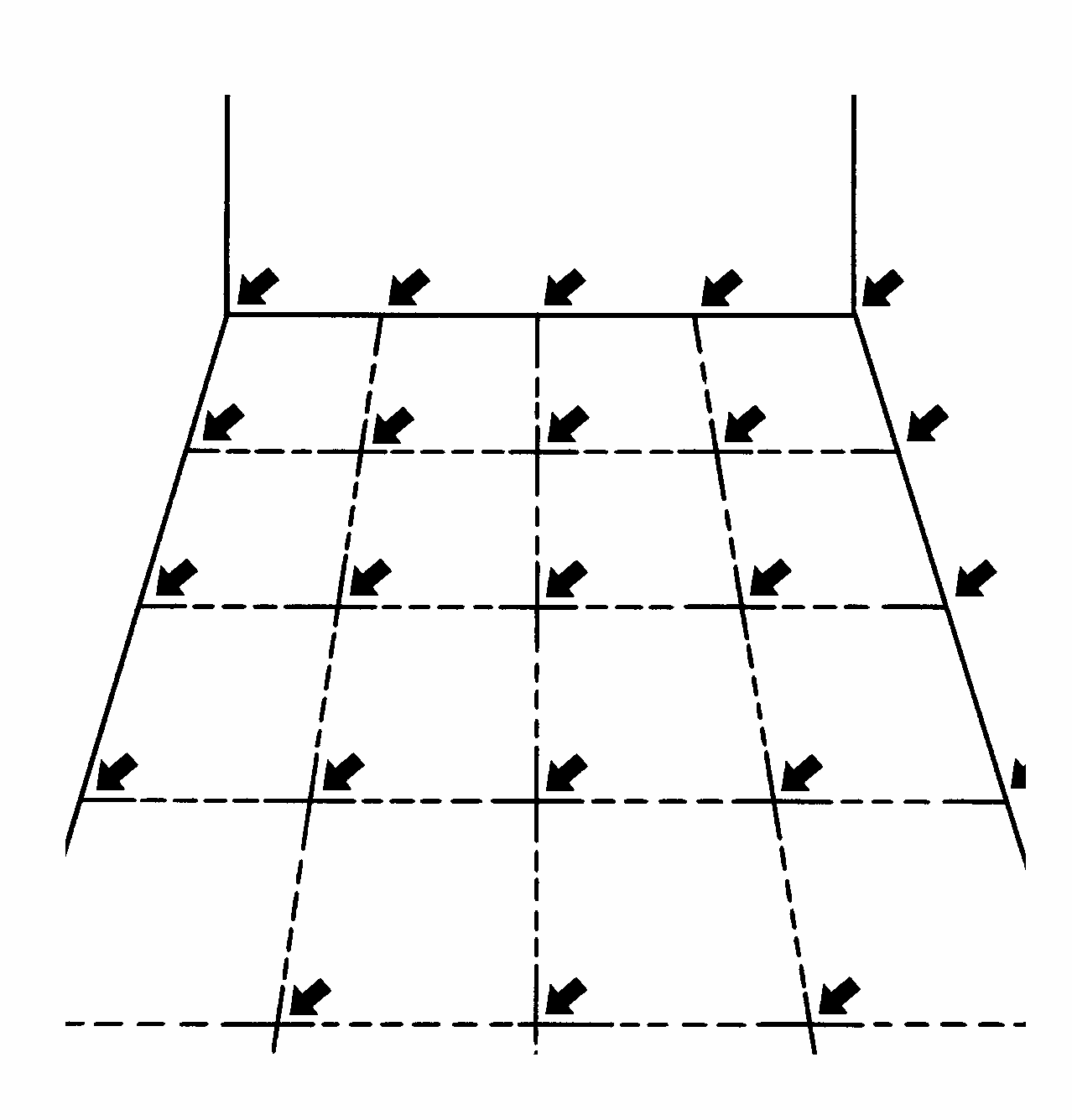
When the areas of the subfloor with the highest moisture content have been detected the residual moisture is determined using a destructive measuring method. Measurements must be made at regular intervals over the entire surface of the floor, with the number of measurements depending on the total floor area, see Fig. 5.
One of the following two destructive measuring methods must be used to determine the residual moisture in the subfloor.
Fig. 6

1. Measurement of moisture content in situ:
The moisture content is determined in a number of drilled holes or channels cast in the floor. The holes are drilled to a depth of approx. ½ x the thickness of the floor construction and with a diameter which allows the measuring instrument's sensor free passage. Carefully vacuum the hole to remove dirt and dust from the concrete. Place the moisture gauge in the drilled hole with a close fitting barrier seal (airtight), see Fig. 6.
The relative humidity of the drilled hole and the residual moisture of the concrete will after some time - up to a period of several days - be in equilibrium and can then be read from the moisture sensor. The temperature of the subfloor must be 17-25 °C (63–77 °F) when measurement is performed.
Fig. 7

2. Measurement of moisture content of samples:
To avoid heating or dampening of the samples these are removed from the floor. Leave the samples in a closed container and take them to a laboratory. Take out samples at the floor depth whose moisture content you wish to determine, see Fig. 7.
NB: Assessment and estimation of the moisture conditions of a structure requires specific technical knowledge and experience. We recommend that you leave this to a moisture specialist.
1.12 STEP SOUND REDUCTION
14, 15, 20.5 and 22 mm (9/16″, 5/8″, 3/4″, and 7/8″) glued floor boards: approx. 9 dB.
For general information about sound and practical guidelines on acoustics in floor constructions, see E 5.0.
1.13 CONSUMPTION OF MATERIALS
Floorboards: approx. 2 % wastage.
Junckers Parquet Glue: approx. 0.8 litres per m² (0.02 gal/ft² or 27 fl oz/ft²) (incl. waste).
Junckers SMP Liquid Moisture Barrier 1.0: 250 g per m² (≈0.051 lb/ft²) as moisture barrier and 120 g per m² as primer (≈0.025 lb/ft²)
Junckers metal adhesive spatula B12: 1 pcs.
Spacers: 25 pcs. per linear metree (7.6 pcs/ft) floor length.
2.0 INSTALLATION INSTRUCTIONS
2.1 MOISTURE READING AND PROTECTION
Concrete floors:
The residual moisture in the subfloor must not exceed 65 % RH, and this must be checked by measuring, see section 11. Measurement of moisture in subfloors under “Specifier´s instructions”.
The floor surface is divided into a grid of modules of approx. 5-10 m2 (54–108 ft²) each. The measurements are then taken at each intersection in the grid, using e.g. a capacitive moisture gauge to find the areas with the highest RH. The residual moisture in the areas with the highest RH is then measured using a destructive measuring method.
Some knowledge and experience of moisture measurement is required for the interpretation and evaluation of the moisture content of a structure. Such measurements should therefore be carried out by an expert.
Use Junckers SMP Liquid Moisture Barrier 1.0 in case of:
- The subfloor has a high absorption capacity. A moisture barrier ensures optimum adhesion.
- Underfloor heating. The underfloor heating system must be switched off during installation.
- The allowed maximum residual moisture content is exceeded.
2.2 APPLYING ADHESIVE
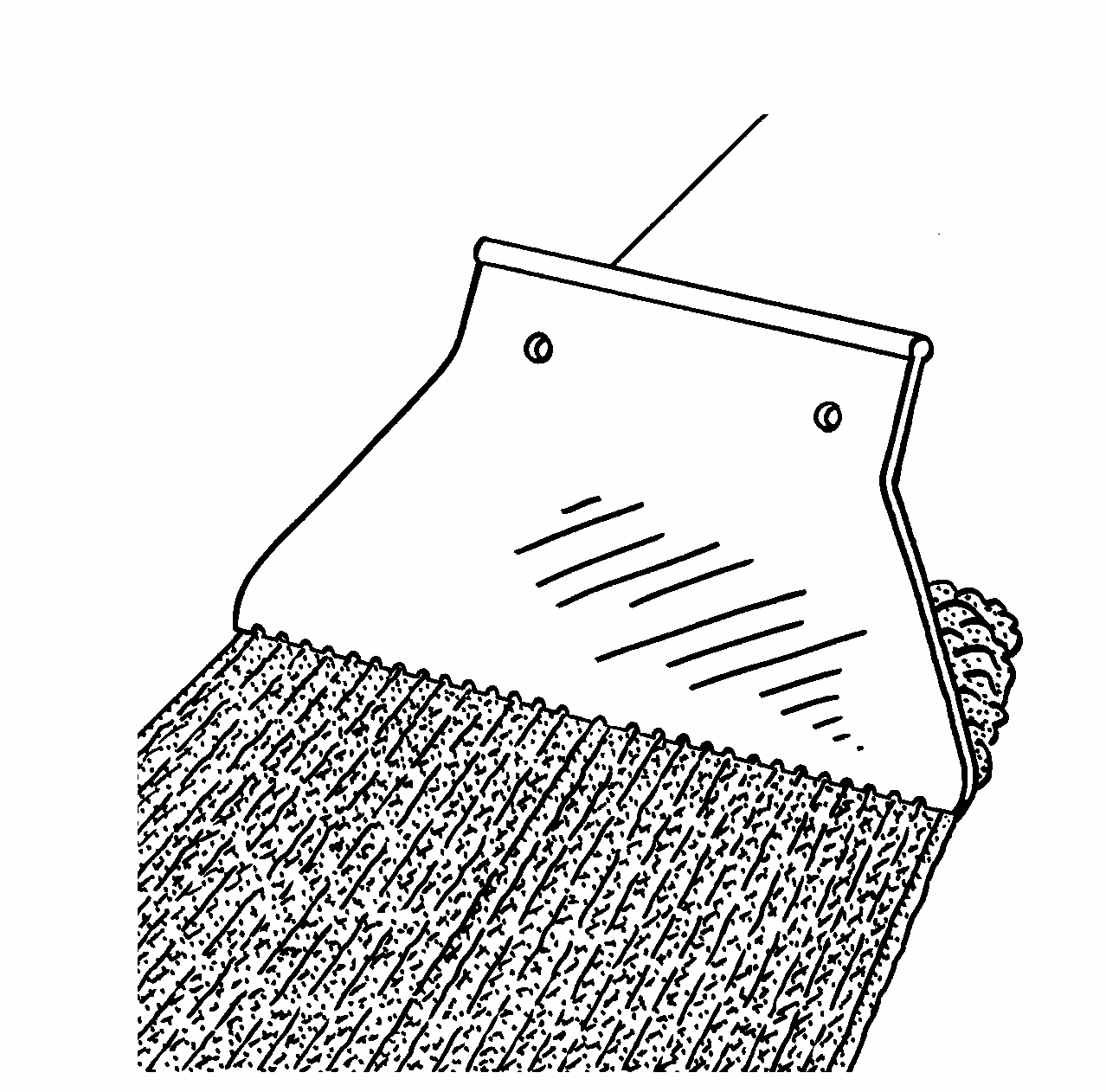
Make sure to choose the correct spatula in order to leave the correct amount of adhesive on the subfloor.
Junckers metal spatula B12: The spatula is held at an angle of 45°. Apply 0.8 litre per m² ( 27 fl oz/ft²) on an area equivalent to 3-4 rows of floor boards at a time. Never exceed an area in which the floorboards can be fitted within 40 minutes.
2.3 LAYING OF FLOOR BOARDS
The floorboards must be installed according to the guidelines noted in section 9 "The 10-board rule under “Specifier´s instructions”.
Press the floorboards firmly into the wet adhesive and place the spacers in between every row at a distance of maximum 900 mm (35 7/16") in order to achieve the required 10-board measure, 10 BM. The 10-board measurement must continuously be checked during installation.
Spacers can be removed and reused, but while installing the floor, make sure always to have spacers placed at a minimum of 3 metres (9′ 10″) in the laying direction. This ensures sufficiently drying time of the adhesive.
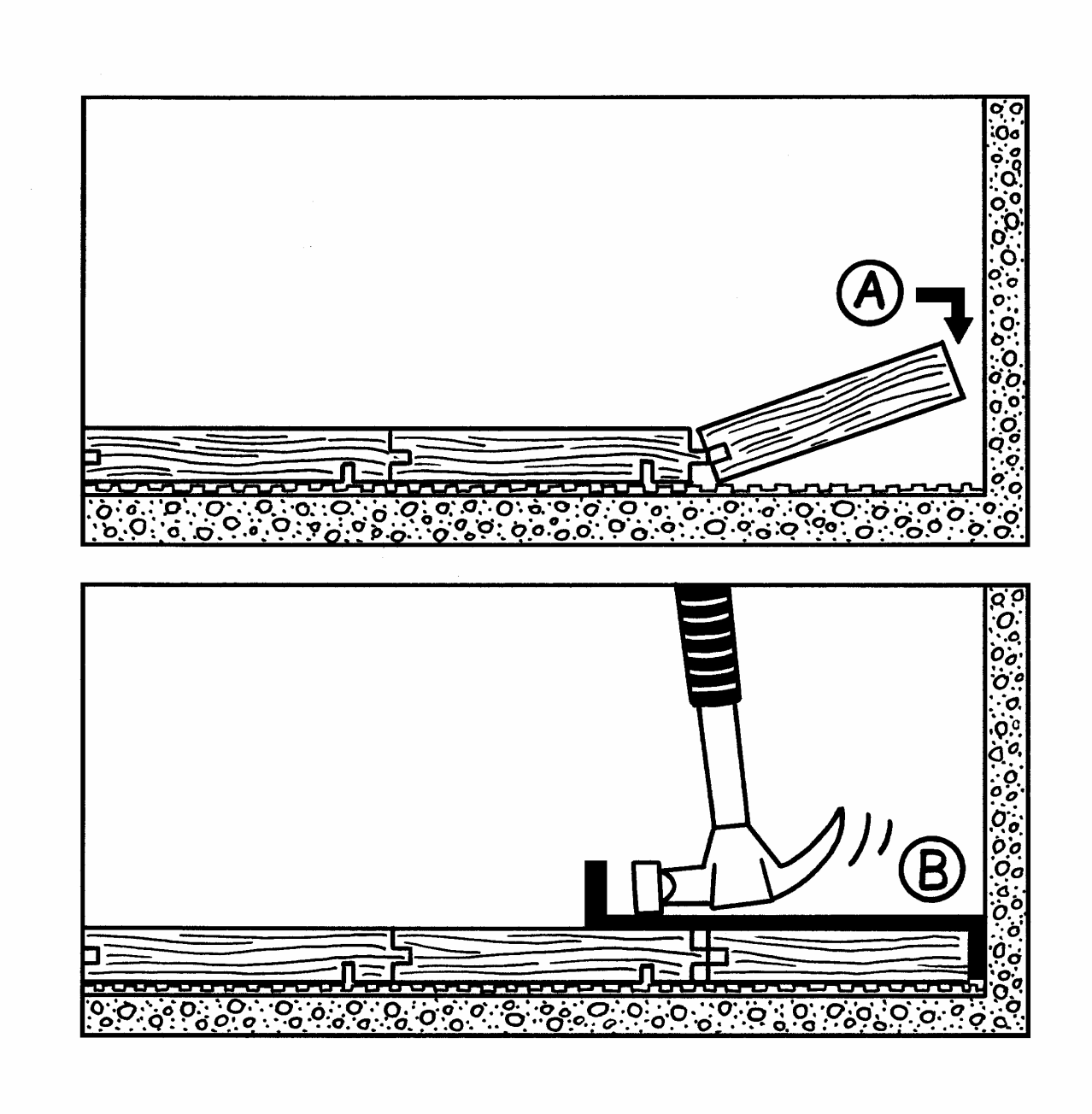
2.4 DISTANCE TO WALLS AND FIXED INSTALLATIONS
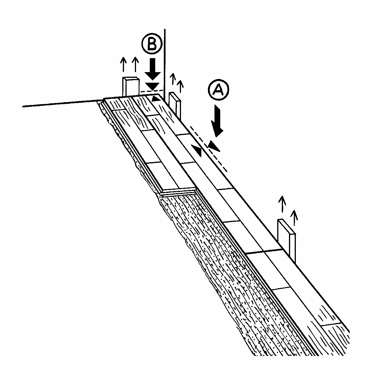
Expansion gaps to walls and fixed installations must be 1.5 mm per running metre of floor width on each side (A), and 1 mm per running metre of floor length at each end (B), all with a minimum size of 12 mm (UK: 15 mm).
Use temporary spacers or wedges between the wall and the floorboards to form the expansion gap.
2.5 FLOOR PATTERN
Install the floorboards in a random joint pattern. Distribute the header joints as far apart as possible. The distance between the floorboard header joints in two successive rows should be at least 250 mm (9 13/16″).
Stave joints in one row of floorboards should not be in line with stave joints in a neighbouring row, but must be spread as far as possible (min. 50 mm (2'')). To avoid waste, the off cut from the last completed row is used to start one of the following rows.
Cut the last row of floorboards to form the correct size of expansion gap at the wall (A). Use a joint puller (B) to slot the last floorboard into place. Remove temporary spacers or wedges before installing skirtings.
2.6 PIPES, DOOR FRAMES, THRESHOLDS
Around pipes, drill a hole in the floorboard to accommodate the pipe. The space around the pipe must be the same as the expansion gap at the wall.
A tapered wedge is cut out, so that it can be glued in place. This gap is covered using a radiator pipe cover.
At door frames and architrave’s, cut the base of the frame and architrave to allow the floor to fit underneath.
At the threshold the expansion gap can be covered by a threshold strip or, if levels reduce, fit a ramp.